Alternatively, these websites may already contain answers to the topic :
T
Tracking error is the time interval between the ...
Tuning is a particular method of dynamically optimizing ...
see Angle Terms
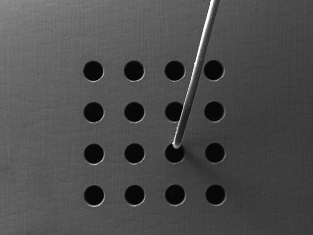
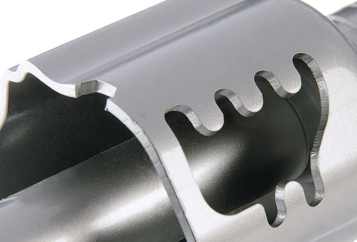
도구로서의 레이저
SCANLAB의 스캔 솔루션은 레이저를 범용 도구로 변환하여 재료에 기능과 가치를 더할 수 있게 합니다. SCANLAB의 폭넓은 스캔 솔루션 제품군은 더 빠른 속도, 더 뛰어난 정밀성 또는 친환경성에 대한 요구를 충족하도록 도와 줍니다.