



More Precision in Laser Material Processing
Laser material processing plays a critical role in various high-precision manufacturing applications. Processes such as display foil cutting, two-photon polymerization, the creation of complex 3D microstructures, selective laser etching, and glass processing place high demands on accuracy, stability, and process control. These applications often involve intricate geometries, sensitive materials, and tight tolerances, making consistent and reliable results difficult to achieve. In response to these technical challenges, new laser scan systems are under development to improve precision, flexibility, productivity and process reliability.
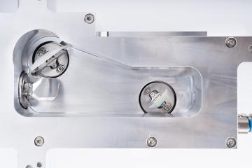
In this field SCANLAB’s new pivotSCAN represents a significant advancement. Designed with a single pivot-point architecture, this scanner offers exceptional telecentricity, beam stability, and optical precision. This article provides a detailed examination of the technology concept, specifications, applications, and comparative advantages.
Historical Perspective: From Galvanometers to pivot-point architecture
Laser scanning systems have evolved significantly since the early days of galvanometer-based scanners. Traditional two-mirror systems, while effective, have struggled with maintaining beam perpendicularity across wide scan fields. This limitation, known as non-telecentricity, introduces angular deviations that can compromise precision, especially in high-resolution or depth-sensitive applications. In glass processing the refraction at the glass surface can lead to significant aberrations, mainly consisting of astigmatism, that is avoided under perpendicular incidence.
The ‘pivot architecture’ scan head addresses this challenge with a three-mirror configuration and a fixed pivot-point design. This ensures that the deflected laser beam always originates from a single, stable point, improving the consistency of beam incidence across the entire scan area.
Innovative technical design eliminates errors
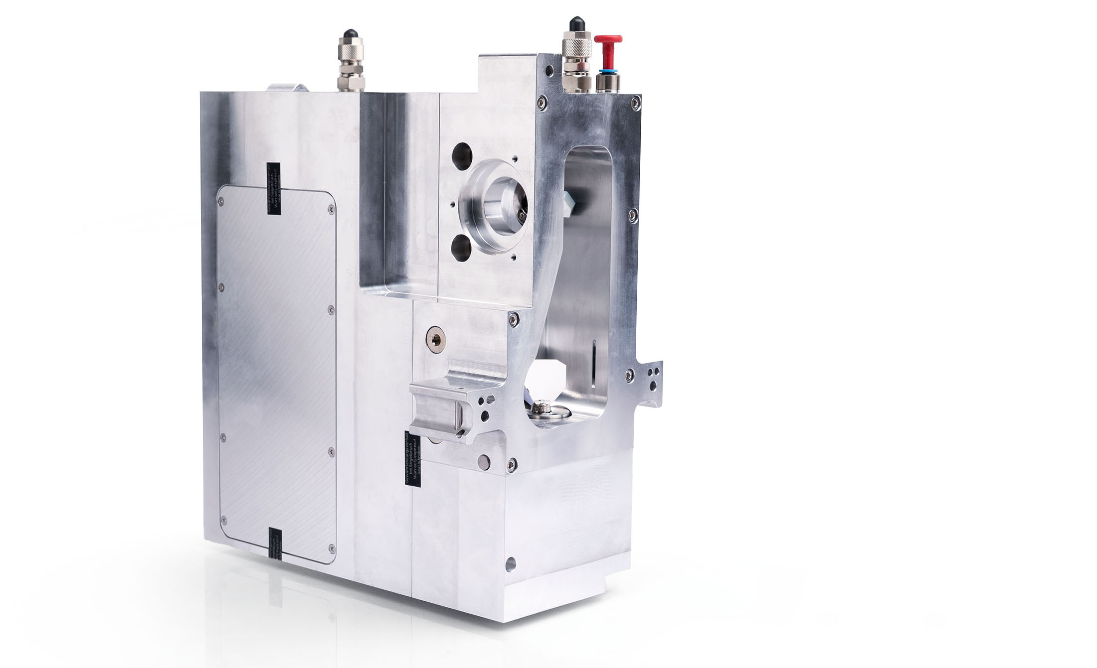
The core of the pivotSCAN is a three-mirror optical system. The mirrors are arranged in a way that the final mirror acts as the origin of the beam’s deflection. In combination with a telecentric scan lens this configuration eliminates parallax errors and angular inconsistencies, ensuring that the beam remains perpendicular to the work surface across the entire scan field.
In standard 2-axis systems, the angle of incidence can vary with telecentric lenses even when mirror positions are perfect by up to 2° from center to edge. The pivot architecture reduces this variation to 0.3°, and with a custom f-theta lens, this can be minimized further. This level of control is critical for applications where even slight angular deviations can affect material interaction. Especially when there is an interface to an optically denser medium this avoids astigmatism.
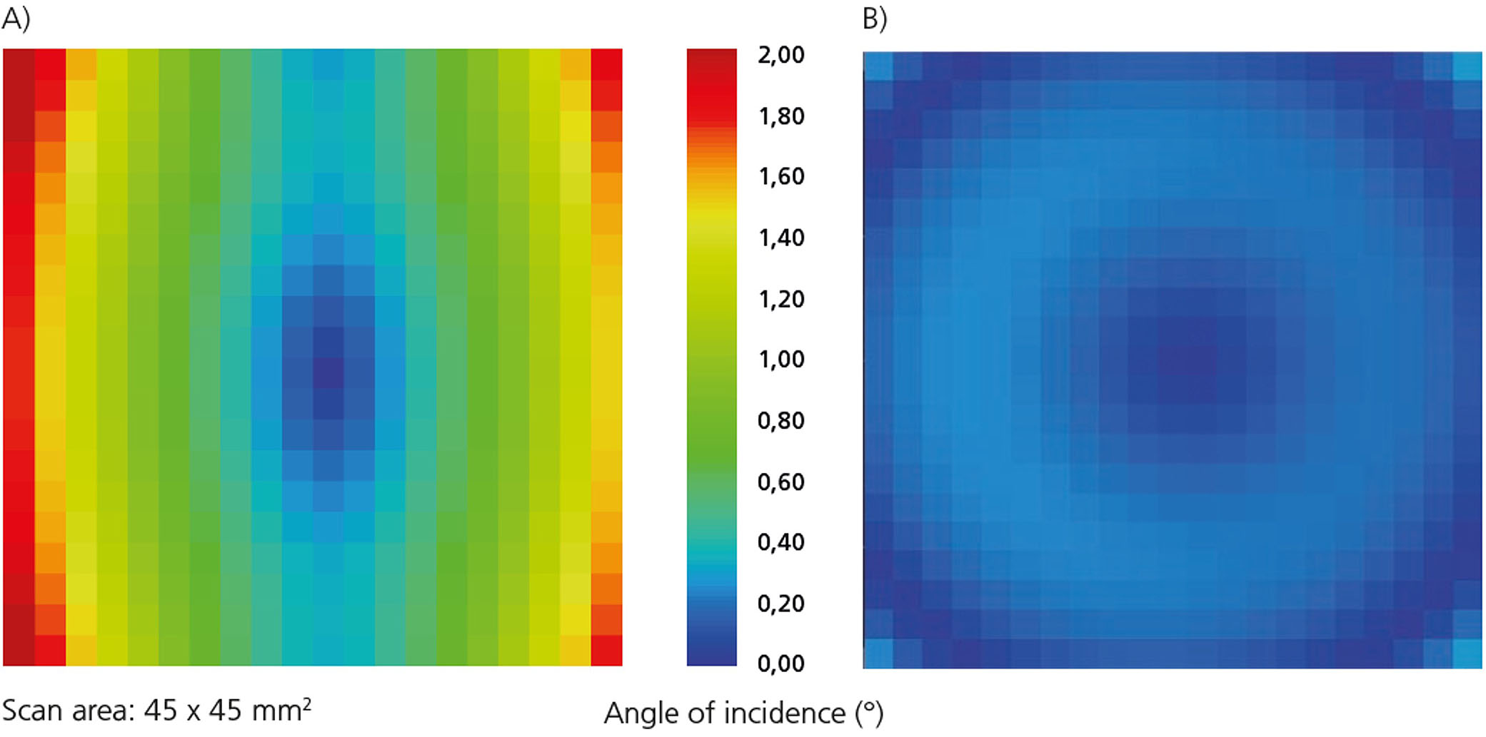
Figure 2 As a result of non-telecentricity the incident angle varies over the field of view of a standard 2-axis scan system (A). pivotSCAN greatly improves telecentricity (B). The angle of incidence with the 2-axis scan system varies between 0° in the center and < 2° at the edge of the field. With three mirrors the angle varies between 0° and 0.3°. The remaining non-telecentricity is completely caused by the nonoptimized f-theta lens (f=100 mm, fused silica). If a custom f-theta lens is used this value can be improved further.
Well studied technical specifications result in precision metrics
The pivot-point architecture system offers a scan area of 45 × 45 mm² at f = 100 mm, with a 14 mm aperture and a typical scan angle of ±0.34 radians. Operating at a wavelength of 1034 nm, it supports laser powers up to 200 W. The system achieves a pivot point accuracy of 100 µm, with zero tracking error, and can accelerate at 48,000 rad/s², reaching speeds of 20 rad/s. The general power requirements are 48 V DC (±2 V) at 5 A, and the system interfaces digitally via SL2-100. The scanner weighs 10 kg and requires SCANmotionControl as control platform.
The scanner is engineered for long-term operational stability. After a 30-minute warm-up, it exhibits an 8-hour drift of 40 ppm gain and 60 µrad offset. Even after 24 hours of continuous operation, these values remain consistent, ensuring reliable and repeatable performance in demanding environments.
Integrated control for precise processing
The SCANmotionControl software increases the degrees of freedom in laser process control. It guarantees exact synchronization of laser parameters and scan head trajectories. The control software calculates optimal motion paths based on predefined machining patterns and process parameters, while accounting for the physical limitations of the scan head.
This advanced control system enables users to define parameters such as process speed, pulse spacing, and energy density with high granularity. The software then computes the ideal combination of scan speed and laser power to achieve consistent energy input across the workpiece. This is particularly important in applications requiring uniform material interaction, such as additive manufacturing, microstructuring, and selective laser etching.
The software is implemented as a dynamic program library (DLL) and is compatible with RTC6 control boards. It supports real-time execution, system parameter configuration, and simulation of scan paths. The simulation environment allows users to evaluate trajectory planning and visualize dynamic values such as scan head position and laser control signals before execution.
Additionally, features like Sub Cycle Switching enable precise laser modulation for short scan lines at high speeds, supporting up to ten switch events within 10 µs. This contributes to improved dimensional accuracy and reduced processing time, particularly in complex geometries.
Refractive boundaries in high-NA focusing
When a tightly focused laser beam with a high numerical aperture (NA) enters a boundary between two media with differing refractive indices—such as from air (low index) into glass or polymer (high index)—under an oblique angle, it experiences a form of aberration known as astigmatism. This effect arises due to the difference in focal lengths for rays in the tangential and sagittal planes, caused by the refraction at the interface.
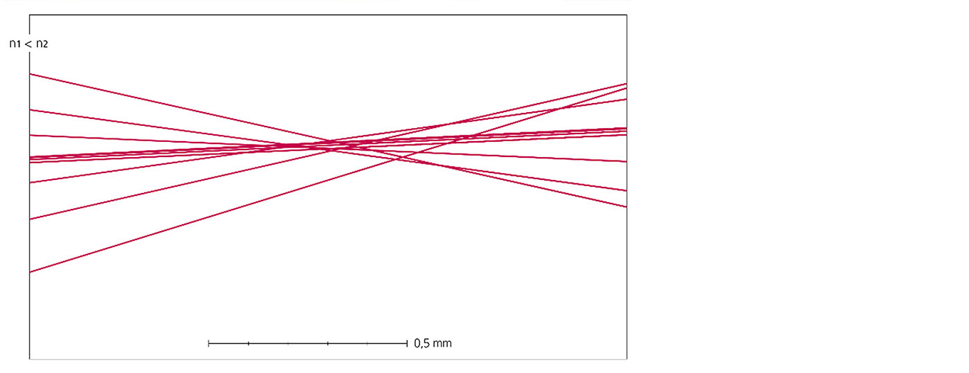
In high-NA systems, where the convergence angle of the beam is large, even small deviations from normal incidence can lead to significant astigmatic distortion. This results in the focal spot elongating along one axis, degrading the beam quality and reducing the intensity at the focal point. The consequence is a deterioration in the precision and efficiency of processes such as laser microfabrication, two-photon polymerization, or subsurface structuring.
This phenomenon is particularly critical when the beam is focused inside the denser material, as the refractive index mismatch causes the wavefronts to bend asymmetrically. The resulting astigmatism cannot be fully corrected by conventional spherical or aspheric optics, especially in dynamic scanning systems. Compensation strategies may include the use of adaptive optics, beam shaping elements, or pre-compensated optical designs.
The new scan system addresses this challenge through its innovative optical design and precise control capabilities. By maintaining a fixed pivot-point and ensuring telecentricity across the scan field, the scanner minimizes the angular deviations that contribute to astigmatism. This results in a more uniform focal spot and improved beam quality, enhancing the precision of laser processing applications.
The impact of this effect has been studied in the context of high-NA lithography and microscopy systems, where maintaining a diffraction-limited spot is essential for resolution and throughput. Understanding and mitigating astigmatism at refractive boundaries is therefore a key consideration in the design and application of high-precision laser scanning systems.
Applications with delicate accuracy and without repositioning
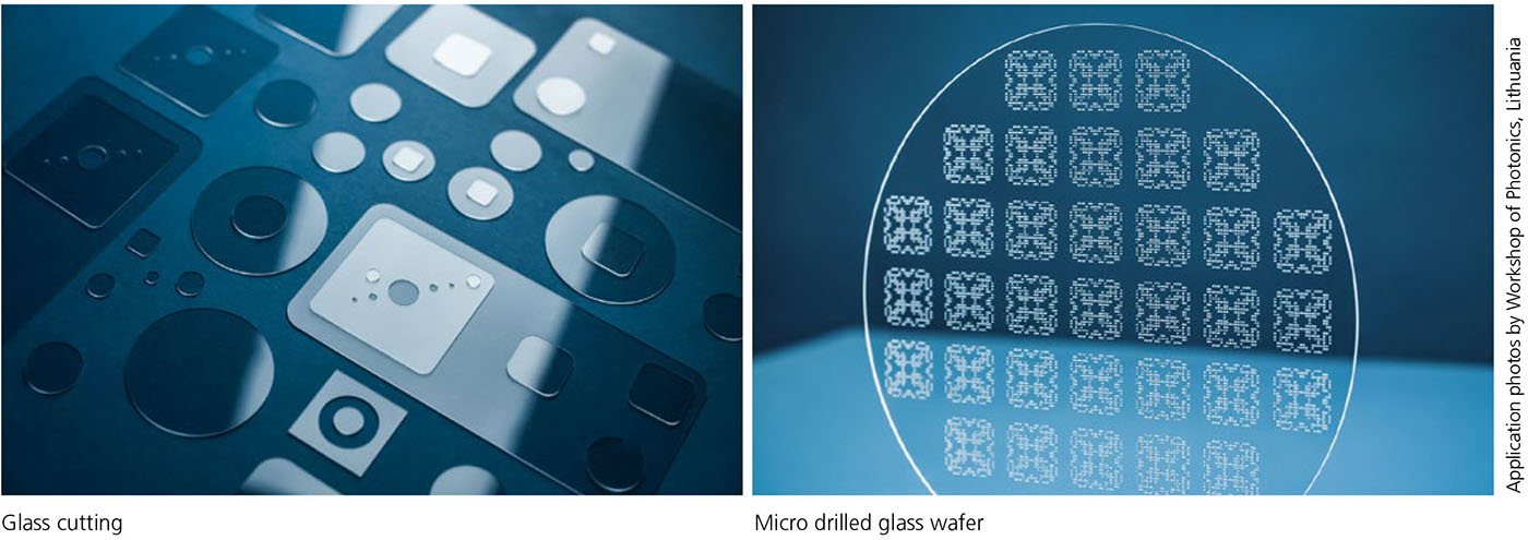
The pivot-point architecture scanner is suitable for a variety of high-precision applications. In display foil cutting, it enables full-field processing, allowing entire workpieces to be scanned without repositioning. In two-photon polymerization, the scanner’s telecentricity ensures that the laser beam enters the photoresist at a consistent angle, which is crucial for building intricate 3D microstructures. In selective laser etching, the scan system enhances edge definition and uniformity, particularly at the solid/air interface. In glass processing, such as micro-drilled wafers, the system’s precision enables the creation of features that are both delicate and dimensionally accurate.
One of the most promising application is TGV (through glass via hole) drilling. Here the glass is modified with a USP laser and afterwards the material is removed by chemical etching. The process requires only a single shot or burst and can therefore be carried out with a fixed optic and a stage at reasonable rates (1000 Hz). However, if a scanner could be applied this frequency can be more than doubled, as the scanner could meander in a small field of view and process the holes without decelerating or accelerating. This so called ‘shot sequence’ is a feature of SCANLAB’s new control architecture SCANmotionControl. Until now the process was not widely transferred to scanner optics as telecentricty is key for a proper hole generation. With the new pivot-point scanner the necessary telecentricity can be reached in the larger field of view an thereby boost productivity.
Comparison with traditional scanners
The combination of a traditional 2-axis scanners combined with a telecentric scan lens suffers from inherent limitations. The dual-mirror design introduces angular variation of the incident beam (even with perfectly positioned mirrors) tafter the f-theta lens that becomes more pronounced at the edges of the scan field. This can lead to inconsistent focus, reduced resolution, and increased optical aberrations.
A pivot architecture scan head with three mirrors addresses these issues with its single pivot-point design, ensuring that the beam path remains consistent regardless of scan position. This improves focus quality and simplifies optical alignment, reducing setup time and maintenance. The scanner’s integration with a control platform allows for real-time beam correction, making it ideal for dynamic applications where precision must be maintained during rapid motion.
A third dimension for future requirements
The pivot-point architecture system is a platform for future advancements. Adding a third dimension to laser processing, opens up new possibilities. Adding a z-shifter, like excelliSHIFT, allows the system to operate in various z positions and enable three dimensional paths. Further new applications can be addressed. With its innovative design, robust performance, and forward-thinking architecture, the new system concept redefines laser scanning. Whether in microfabrication or scientific research, a pivot-point scanner delivers the accuracy, consistency, and control required for challenges that couldn’t be faced easily before.
Product Information
pivotSCAN – High precision scan system for superior telecentricity
Author
Holger Schlüter, SCANLAB GmbH